Microbit Robot Car- Build
Introduction
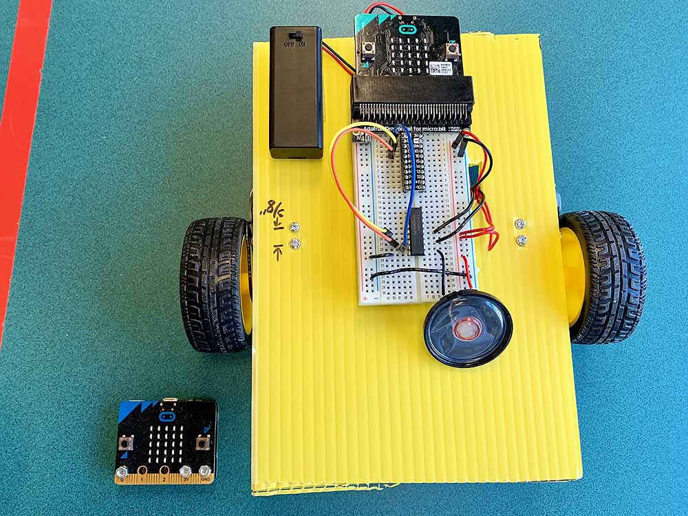
The following describes a version of the robotic vehicle made using a BBC MicroBit in place of an Arduino.
A homemade cut-out piece of Coroplast or cardboard is used in place of the stock plexiglas plate that comes with the Emgreat robot chassis kit. This is done because the Emgreat chassis is about an inch too narrow to fit the battery pack on the bottom, and about an inch too short to permit free rotation of the caster wheel.
The major electrical components are attached using Velcro, to make them easier to reposition if needed.
The Microbit cannot directly supply enough current to drive the motors, so transistor drivers must be used.
While the Arduino version of the robot car used an L298 H-bridge module to control the motors, this requires six(6) control lines, which are in short supply on the Microbit. I realized it was not essential that the motors be able to spin backwards. So in place of the L298, the Microbit version of the robot uses a ULN2803A 8-channel Darlington transistor array as a motor driver. This can be used to drive a speaker, lights, and other devices as well, as the Microbit has six(5) general purpose I/O lines on pins 0,1,2,8, and 16. Pin 0 can be used for audio output. The other pins can be tricky to use, as they are shared with the built-in LEDs.
Alternatively, one could use discrete transistors, such as the TIP120; however, this would require using many more parts and wires.
To access the pins on the MicroBit, this design uses the Adafruit Dragontail for Microbit, which plugs directly into the breadboard, making the pins easily accessible, as well as connecting the 3V power bus.
Wireless Remote:
To control the robot wirelessly via Bluetooth, you can use a second Microbit, powered either by the AAA battery pack that comes in the Microbit Go kit, or a coin cell battery pack, the MI Power Board for Microbit.
Both Microbits need to be set to the same Radio channel.
Parts List
VEHICLE:
Emgreat Motor Robot Chassis Kit
Microbit Go Kit
ULN 2803A 8-channel Darlington Array
Adafruit Dragontail for Microbit #3695
Half-size Breadboard #64
Adafruit 4x "AA" Battery Box With Switch #830
22 gauge solid hookup wire, assorted colors
Mini Metal Speaker with Wires #1890
Corrugated plastic or cardboard
Scotch 1" x 1" fastener strips
REMOTE:
Microbit Go Kit
MI Power Board for the BBC Microbit
Tools:
Razor Knife
Soldering Iron
Wire Stripper
Hot Glue Gun
Mini Screw Driver(comes with chassis)
Sharpie Marker
Parts:
Assembly:
- Cut out 6" x 8" piece of corrugated plastic; mark position of holes for caster wheel and motor brackets.
- Solder 8" red and black wires to each of the two motors; hot glue to motors for strain relief.
- Attach the motors to the baseplate with the provided metal brackets.
- Attach the caster wheel to the bottom end.
- Attach the 4 x AA battery box(with batteries) to the underside of the chassis,, using velcro squares, between the motors and the caster wheel; this gives the best traction.
- Insert the MicroBit Dragontail into the breadboard; attach the breadboard to the top of the chassis using double-stick tape or velcro strips
- Attach the 2xAAA 3V battery pack to the chassis using velcro strips; insert the JST battery plug into Microbit board battery socket.
- Insert the ULN 2803A Darlington array IC into the breadboard across the 'valley'.
- Make a small 1/4" x 1/4" hole in the chassis board next to the breadboard.
Wiring:
- Thread 6V wires up through hole and plug into right-hand power bus on breadboard.
- Connect wire between the left and right-hand ground buses on the breadboard.
- Connect black wire between pin 9 on IC and ground.
- Connect red wire between pin 10 and +6V power buss
- Connect jumper wires:
- Between Pin 0 on dragontail and Pin 8 on 2803A
- Between Pin 1 on dragontail and Pin 6 on 2803A
- Between Pin 2 on dragontail and Pin 4 on 2803A
- Between Pin 8 on dragontail and Pin 2 on 2803A
- Connect Motor 1 wires to +6V buss and Pin 13 on 2803A
- Connect Motor 2 wires to +6V buss and Pin 15 on 2803A
- Connect speaker wires to +6V and Pin 11 on 2803A
Programming 1: Motor Test
Programming 2: Bluetooth Radio Remote Control
